Instructions to Hardware: A Gentle Introduction to Computer Architecture, ARM Assembly, and Verilog
A hands-on workshop guide connecting C source code to ARM assembly, machine code, a simplified single-cycle processor, SystemVerilog simulation, and GTKWave inspection.
On this page
This handout is designed to be followed from top to bottom during the workshop and reused later as a laboratory reference. The presentation is the primary source for the sequence, terminology, examples, and commands. Where the software-installation details were checked against current online documentation, those items are marked as web-verified and linked to official project or vendor pages.
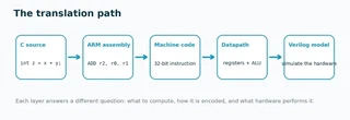
Workshop question: How does a statement such as
z = x + y;become an electrical operation inside a processor?
Table of Contents
- Table of Contents
- 1. Workshop Overview
- 2. Learning Objectives and Scope
- 3. Required Software
- 4. Workshop Files
- 5. Toolchain Overview
- 6. What Is an ARM Instruction?
- 7. ARM Registers and Load/Store Architecture
- 8. Hands-on 1 — Generate ARM Assembly from C
- 9. Read the Generated Assembly
- 10. Machine Code and
memfile.dat - 11. A Quick Look at A32 Instruction Fields
- 12. The Simplified ARM Processor
- 13. The Single-Cycle Datapath
- 14. Verilog/SystemVerilog Essentials
- 15. Hands-on 2A — Build the 4-bit ALU
- 16. Hands-on 2B — Test and Inspect the ALU
- 17. Hands-on 3A — Write the Deterministic ARM Program
- 18. Hands-on 3B — Generate
memfile.dat - 19. Separated Processor and Testbench Architecture
- 20. Hands-on 3C — Compile and Run the Processor
- 21. Runtime Cycle Control and Recompilation Rules
- 22. GTKWave Inspection of the ARM Execution
- 23. Expected Processor Behaviour and Verification Checklist
- 24. Troubleshooting
arm-none-eabi-gcc: command not foundiverilog: command not foundorvvp: command not foundUnable to open memfile.dat/$readmemherror- File appears missing even though you saved it in Notepad
- Verilog syntax error in the ALU exercise
arm_single.vcdis not created- GTKWave opens but no traces are visible
- Bus values are hard to read
- Unknown
xvalues appear - The final value is wrong
- The C-generated assembly differs from the handout
- Fast recovery sequence
- 25. Suggested Exercises and Extensions
- 26. Summary and References
1. Workshop Overview
The workshop connects five views of the same computation:
C source
   ↓
ARM assembly
   ↓
32-bit machine code
   ↓
single-cycle datapath
   ↓
Verilog/SystemVerilog model + simulation waveform
The emphasis is not memorizing ARM encoding or HDL syntax. The goal is to see how software-visible instructions map onto registers, an ALU, memories, control logic, and observable digital signals.
The presentation introduces the layers in this order: source code, ARM assembly, machine code, instruction fields, a simplified processor, Verilog/SystemVerilog, testbenches, Icarus Verilog, and GTKWave. This handout keeps that teaching progression but moves the simple_sum.s → memfile.dat generation immediately before the full-processor simulation so that the laboratory workflow is executable from start to finish.
Suggested live-workshop use: follow the numbered hands-on procedures. Explanatory subsections can be read in more detail after the workshop.
2. Learning Objectives and Scope
By the end of the workshop, you should be able to:
- explain the path C → assembly → machine code → datapath → HDL simulation;
- recognize the roles of basic AArch32 registers such as
r0,r1,r2,sp,lr, andpc; - explain the load–operate–store mental model;
- generate A32 assembly using
arm-none-eabi-gcc; - inspect machine-code words with
arm-none-eabi-objdump; - describe and simulate a small combinational ALU;
- distinguish a design module from a simulation testbench;
- compile the supplied single-cycle processor and its separate testbench using Icarus Verilog;
- change simulation length using
+CYCLES=Nwithout recompiling; - inspect the ARM execution in GTKWave and identify the successful final store.
This is deliberately a gentle introduction. The workshop does not attempt to cover pipelines, hazards, caches, speculative execution, virtual memory, detailed ABI rules, synthesis, place-and-route, or timing closure. Real Arm processors are much more sophisticated than the educational single-cycle model used here.
3. Required Software
Recommended platform: Windows 10/11, 64-bit, using the MSYS2 UCRT64 terminal. The presentation uses this Windows-native setup to avoid switching between Windows and WSL during a short laboratory session. MSYS2 documents UCRT64 as its modern Universal C Runtime environment and made it the default over MINGW64; the current package pages provide all tools used here.
3.1 Software and official pages
| Software | Purpose in this workshop | Official page | Recommended installation |
|---|---|---|---|
| MSYS2 | UCRT64 terminal and pacman package manager | MSYS2 / Installer | Current 64-bit installer; open MSYS2 UCRT64 |
| Native GCC | General C compiler used in the workshop toolchain | MSYS2 GCC package | UCRT64 package |
| Arm bare-metal GCC | Generates A32 assembly and assembles simple_sum.s | MSYS2 Arm GCC package | UCRT64 package |
| Icarus Verilog | Compiles Verilog/SystemVerilog designs and testbenches | Icarus Verilog documentation / MSYS2 package | UCRT64 package |
| GTKWave | Opens VCD waveform files | GTKWave / MSYS2 package | UCRT64 package |
Web-verified on 2026-08-11: the MSYS2 repository listed Arm GCC 16.1.0-1, Icarus Verilog 13.0-2, and GTKWave 3.3.127-1 in UCRT64. Exact package versions can change; use the current MSYS2 packages rather than pinning these versions.
3.2 Install MSYS2
- Download the current 64-bit installer from the official MSYS2 installer page.
- Install to the default short path such as
C:\msys64, unless your laboratory has a managed-software policy. - From the Windows Start menu, open MSYS2 UCRT64. Do not use the plain MSYS2 MSYS shell for these package commands.
3.3 Update the package database and installed packages
Run in MSYS2 UCRT64:
pacman -Syu
If MSYS2 asks you to close the terminal after updating core components, close all MSYS2 windows, reopen MSYS2 UCRT64, and run:
pacman -Syu
again.
3.4 Install the workshop packages
pacman -S --needed \
  mingw-w64-ucrt-x86_64-gcc \
  mingw-w64-ucrt-x86_64-arm-none-eabi-gcc \
  mingw-w64-ucrt-x86_64-iverilog \
  mingw-w64-ucrt-x86_64-gtkwave
The Arm GCC package also pulls in the corresponding Arm binutils, including arm-none-eabi-objdump. The Icarus package contains both iverilog and vvp.
3.5 Verify the installation
gcc --version
arm-none-eabi-gcc --version
arm-none-eabi-objdump --version
iverilog -V
vvp -V
gtkwave --version
Pass condition: each command prints version information rather than command not found.
3.6 Create a workshop folder
mkdir -p ~/workshop
cd ~/workshop
pwd
You may instead use another writable folder. The important rule for the processor simulation is that arm_single.sv, arm_single_tb.sv, and memfile.dat must be in the working folder when you run the simulation.
4. Workshop Files
Before beginning the processor simulation, download the three required processor files and place them in the same working folder.
4.1 Required processor files
| File | Purpose | Download | Place it in |
|---|---|---|---|
arm_single.sv | Single-cycle ARM processor plus instruction and data memories | Download arm_single.sv | ~/workshop |
arm_single_tb.sv | Separate simulation testbench containing clock/reset generation, +CYCLES=N control, self-checking, and waveform dumping | Download arm_single_tb.sv | ~/workshop |
memfile.dat | ARM machine-code program loaded by the processor’s instruction memory | Generate it in Hands-on 3B (not provided as a download) | ~/workshop |
After downloading, your workshop directory should contain:
workshop/
├── arm_single.sv
├── arm_single_tb.sv
└── memfile.dat
4.2 Files students create or generate during the workshop
| File | Purpose | Action |
|---|---|---|
add.c | Tiny C function for compiler observation | Create during Hands-on 1 |
add_armv7a.s | Compiler-generated assembly | Generated by GCC |
simple_alu.v | 4-bit combinational ALU | Create during Hands-on 2 |
tb_simple_alu.v | ALU testbench | Create during Hands-on 2 |
alu_sim | Compiled Icarus simulation | Generated by iverilog |
alu.vcd | ALU waveform | Generated by vvp |
simple_sum.s | Deterministic A32 demo program | Create during Hands-on 3 |
simple_sum.o | Assembled object file | Generated by GCC |
memfile.dat | One machine-code word per line for instruction memory | Generate from simple_sum.o |
arm_single.out | Compiled processor simulation | Generated by iverilog |
arm_single.vcd | Full processor waveform | Generated automatically by the revised testbench |
Recovery aid: the reference copies are included so a student who loses time to an editing error can rejoin the workshop. The live exercise is more useful if you create the files yourself first.
5. Toolchain Overview
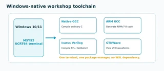
The tools play different roles:
C source ──arm-none-eabi-gcc──> ARM assembly

ARM .s ──arm-none-eabi-gcc -c──> object file
object file ──arm-none-eabi-objdump──> assembly + machine words

Verilog/SystemVerilog sources ──iverilog──> compiled simulation
compiled simulation ──vvp──> execution + VCD file
VCD file ──gtkwave──> waveform inspection
Why this matters:
iverilogandvvpare separate steps. Icarus documentation describesiverilogas the compiler/driver andvvpas the runtime that executes the compiled simulation.
6. What Is an ARM Instruction?
An instruction is a compact command specifying an operation and its operands. Consider:
ADD r2, r0, r1
ADDis the mnemonic: what operation to perform.r2is the destination: where the result is written.r0andr1are the source operands.
In A32 state, the instruction is represented by a 32-bit machine word. Assembly is written for humans; the processor fetches the encoded word.
The workshop deliberately requests A32/Arm-state output with:
-marm
rather than Thumb output.
Check yourself: Which token selects the ALU operation in
ADD r2, r0, r1?
Answer: the mnemonic/opcode,ADD.
7. ARM Registers and Load/Store Architecture
AArch32 exposes registers r0 through r15. For this workshop, the most useful names are:
r0–r3: commonly used for early function arguments, temporaries, and return values under common AArch32 calling conventions;r13 / sp: stack pointer;r14 / lr: link register, commonly holding a return address;r15 / pc: program counter.
The architecture defines registers and instructions. A calling convention defines how software uses registers during function calls.
7.1 Load → operate → store
ARM is presented here as a load/store architecture: arithmetic operates on register values, while LDR and STR move data between registers and memory.
LDR r0, [r4, #8]    @ r0 <- memory[r4 + 8]
ADD r2, r0, r1      @ r2 <- r0 + r1
STR r2, [r4, #12]   @ memory[r4 + 12] <- r2
The simple mental model is:
Load → operate → store
Do not worry about the full set of ARM addressing modes today. For the workshop, base register plus immediate offset is sufficient.
8. Hands-on 1 — Generate ARM Assembly from C
Estimated time from the presentation: about 10 minutes.
Objective
Compile a small C function to ARMv7-A A32 assembly and identify the function label, registers, arithmetic operation, and return sequence.
Procedure
- In the MSYS2 UCRT64 terminal, make sure you are in your workshop folder:
cd ~/workshop
- Create the file:
notepad.exe add.c
- Enter exactly:
int add(int a, int b) {
    return a + b;
}
Save and close Notepad.
Generate unoptimized assembly:
arm-none-eabi-gcc -S \
  -march=armv7-a -marm -O0 \
  add.c -o add_armv7a.s
- Display the assembly:
cat add_armv7a.s
- Find four features:
- the function label
add:; - registers carrying or temporarily holding the two input values;
- an
addinstruction or equivalent arithmetic operation; - the return sequence, commonly ending in
bx lr.
- the function label
Presentation consistency note: the teaching discussion in the deck explicitly explains the verbose
-O0case and then compares optimization. This handout therefore uses ASCII-O0for the first run. Use-O1in the comparison below.
What the options mean
| Option | Meaning |
|---|---|
-S | Stop after compilation and emit assembly source |
-march=armv7-a | Target the ARMv7-A architecture |
-marm | Generate A32/Arm-state instructions rather than Thumb |
-O0 | Disable optimization for a more direct compiler output |
-o add_armv7a.s | Name the output file |
9. Read the Generated Assembly
Compiler output is not guaranteed to match the slide line for line. GCC version, optimization, and compiler decisions can change register allocation, stack-frame construction, directives, and comments.
A trimmed semantic pattern may look like:
add:
    ...                    @ optional prologue / argument handling
    add   r3, r2, r3       @ arithmetic
    mov   r0, r3           @ place return value in r0
    ...                    @ optional epilogue
    bx    lr               @ return
Focus on meaning:
- Inputs: the first two integer arguments commonly arrive in
r0andr1. - Computation: at
-O0, the compiler may copy, spill, and reload values before the actualADD. - Return: the result commonly ends in
r0;bx lrreturns to the caller.
Compare with optimization
Run:
arm-none-eabi-gcc -S \
  -march=armv7-a -marm -O1 \
  add.c -o add_armv7a_O1.s

cat add_armv7a_O1.s
Ask yourself:
- Which instructions disappeared?
- Is the observable C behavior unchanged?
- Which lines are the actual arithmetic and which support function entry/exit?
Optional machine-code view
arm-none-eabi-gcc -c \
  -march=armv7-a -marm -O0 \
  add.c -o add_armv7a.o

arm-none-eabi-objdump -d add_armv7a.o
This links the human-readable assembly to encoded instructions without requiring you to hand-encode every field.
10. Machine Code and memfile.dat
The simplified processor does not read .s assembly source. Its instruction memory uses $readmemh to read machine-code words from memfile.dat when the simulation starts.
Each line is one 32-bit instruction represented by 8 hexadecimal digits:
Assembly                         Machine code
ADD R3, R1, R2                   E0813002
STR R3, [R0, #248]               E58030F8
B halt                           EAFFFFFE
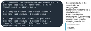
The workflow used later is:
assembly source
      ↓
object file
      ↓
objdump
      ↓
machine-code words
      ↓
memfile.dat
      ↓
instruction memory
Why this matters: compiler-generated C assembly is excellent for learning. For the educational processor, however, a short handwritten
.sfile gives a deterministic instruction sequence that stays within the processor’s supported subset.
11. A Quick Look at A32 Instruction Fields
You do not need to memorize full ARM encoding. The presentation uses only enough decoding to connect a 32-bit word to the processor’s controller.
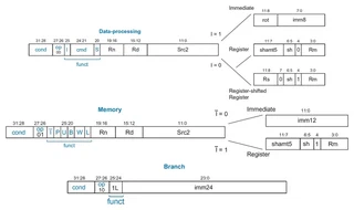
11.1 Condition field
Bits 31:28 are the condition field. In the workshop program, the instructions use condition code:
1110 = E = always execute
11.2 Main operation class
The simplified controller uses bits 27:26 to distinguish broad instruction classes:
00  data processing
01  memory access (LDR / STR)
10  branch
11.3 Example: ADD R3, R1, R2
E0813002
Important fields are:
- condition =
E/ always; - operation class = data processing;
- data-processing opcode =
ADD; Rn = R1;Rd = R3;- register operand
Rm = R2.
11.4 Memory and branch examples
LDR R1, [R0, #0]       @ E5901000
STR R3, [R0, #248]     @ E58030F8
B halt                  @ EAFFFFFE
The single-cycle processor does not implement an OUT or HLT instruction. The workshop models output as a store to a watched address and models halting as an infinite branch plus testbench-controlled $finish.
12. The Simplified ARM Processor
The supplied processor is an educational A32-compatible subset. Its decoder supports the instructions used in the presentation:
ADD
SUB
AND
ORR
LDR
STR
B
The source contains a controller, datapath, register file, ALU, immediate extender, multiplexers, PC logic, instruction memory, and data memory.
This is not a complete modern Arm core. Its purpose is to make instruction execution traceable.
The full demonstration program conceptually performs:
mem[0] = 3
mem[1] = 4

R1 = mem[0]
R2 = mem[1]
R3 = R1 + R2

store R3 to address 0xF8
branch forever
The data memory is not initialized from memfile.dat, so the program first writes 3 and 4 into mem[0] and mem[1] before loading them back.
13. The Single-Cycle Datapath
A microarchitecture is the hardware organization used to implement an architecture. In this teaching model, each instruction completes through the datapath in a single clock cycle.
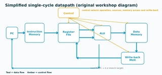
For a register-to-register instruction such as:
ADD r2, r0, r1
trace the operation as follows:
- Fetch: the PC selects a word in instruction memory.
- Decode: instruction fields select
r0,r1, and destinationr2. - Read operands: the register file presents the current source values.
- Execute: control selects the ADD function and the ALU computes the sum.
- Write back: the ALU result is written to
r2.
No data-memory access is needed for this register-to-register ADD.
Check yourself: Which major datapath block is present but bypassed for
ADD r2, r0, r1?
Answer: data memory.
14. Verilog/SystemVerilog Essentials
Verilog describes hardware, not a sequential list of software commands. A module represents logic that exists concurrently.
Three ideas are sufficient for this workshop:
- Module interface: inputs and outputs are signals crossing the hardware boundary.
- Combinational behavior:
always @(*)describes logic whose output responds to current inputs. - Testbench: a separate simulation-only module drives inputs, observes outputs, and can request waveform recording.
A combinational decision network can be written as:
always @(*) begin
    case (op)
        2'b00: y = a + b;
        // ...
    endcase
end
The full processor source uses SystemVerilog constructs such as logic, always_comb, and always_ff. Therefore the processor compile command uses:
-g2012
Icarus documents -g2012 as enabling the IEEE 1800-2012 SystemVerilog language level.
15. Hands-on 2A — Build the 4-bit ALU
Estimated time from the presentation: about 8 minutes.
Objective
Create a four-operation combinational ALU with two 4-bit inputs, a 2-bit operation selector, and a 4-bit result.
Operation table
op | Operation | Expression |
|---|---|---|
00 | ADD | a + b |
01 | SUB | a - b |
10 | AND | a & b |
11 | OR | a | b |
Because y is only four bits wide, arithmetic wraps modulo 16.
Procedure
- Create the source file:
notepad.exe simple_alu.v
- Enter:
module simple_alu(
    input  [3:0] a,
    input  [3:0] b,
    input  [1:0] op,
    output reg [3:0] y
);

always @(*) begin
    case(op)
        2'b00: y = a + b;
        2'b01: y = a - b;
        2'b10: y = a & b;
        2'b11: y = a | b;
    endcase
end

endmodule
- Save and close the file.
Before simulating, predict the outputs for:
a = 6
b = 3
16. Hands-on 2B — Test and Inspect the ALU
Create the testbench
- Create:
notepad.exe tb_simple_alu.v
- Enter:
module tb_simple_alu;

reg  [3:0] a, b;
reg  [1:0] op;
wire [3:0] y;

simple_alu uut (
    .a(a),
    .b(b),
    .op(op),
    .y(y)
);

initial begin
    $dumpfile("alu.vcd");
    $dumpvars(0, tb_simple_alu);

    a = 4'd6;
    b = 4'd3;

    op = 2'b00; #10;
    op = 2'b01; #10;
    op = 2'b10; #10;
    op = 2'b11; #10;

    $finish;
end

endmodule
Compile, simulate, inspect
- Compile:
iverilog -o alu_sim simple_alu.v tb_simple_alu.v
- Run:
vvp alu_sim
- Confirm the waveform exists:
ls -l alu.vcd
- Open GTKWave:
gtkwave alu.vcd
- In GTKWave, select hierarchy
tb_simple_alu, then add:
a
b
op
y
- Zoom to the full
0–40interval.
Expected behavior:
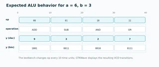
| Time | op | Operation | y decimal | y binary |
|---|---|---|---|---|
| 0–10 | 00 | ADD | 9 | 1001 |
| 10–20 | 01 | SUB | 3 | 0011 |
| 20–30 | 10 | AND | 2 | 0010 |
| 30–40 | 11 | OR | 7 | 0111 |
Engineering habit: predict → edit → compile → simulate → inspect → explain. A tool completing without error is not, by itself, proof that the design is correct.
17. Hands-on 3A — Write the Deterministic ARM Program
The C example was useful for observing the compiler, but the simplified processor supports only a small instruction subset. For a deterministic full-processor demonstration, write the exact assembly program used by the presentation.
Procedure
- In
~/workshop, create:
notepad.exe simple_sum.s
- Enter exactly:
.syntax unified
.arch armv7-a
.arm
.global _start

_start:
    SUB R0, R15, R15      @ R0 = 0
    ADD R1, R0, #3        @ R1 = 3
    STR R1, [R0, #0]      @ mem[0] = 3

    ADD R2, R0, #4        @ R2 = 4
    STR R2, [R0, #4]      @ mem[1] = 4

    LDR R1, [R0, #0]      @ R1 = mem[0]
    LDR R2, [R0, #4]      @ R2 = mem[1]
    ADD R3, R1, R2        @ R3 = R1 + R2 = 7

    STR R3, [R0, #248]    @ write result to testbench output address
halt:
    B halt                @ pseudo-HLT
What the program does
SUB R0, R15, R15makesR0 = 0and uses it as the base address.- The first two
STRinstructions initialize data-memory words 0 and 1. - The two
LDRinstructions read back3and4. ADD R3, R1, R2produces7.- The final
STRwrites7to byte address248 = 0xF8. B haltloops forever as a pseudo-halt.
Why initialize memory in software? The supplied
dmemarray is not loaded by$readmemh; only the instruction memoryimemreadsmemfile.dat.
18. Hands-on 3B — Generate memfile.dat
Procedure
- Assemble the handwritten program:
arm-none-eabi-gcc -c \
  -march=armv7-a -marm \
  simple_sum.s -o simple_sum.o
- Inspect assembly and machine code side by side:
arm-none-eabi-objdump -d simple_sum.o
- Export one machine-code word per line:
arm-none-eabi-objdump -d simple_sum.o | \
  awk '/^[[:space:]]*[0-9a-f]+:/ {print toupper($2)}' > memfile.dat
- Inspect the result:
cat memfile.dat
Expected file:
E04F000F
E2801003
E5801000
E2802004
E5802004
E5901000
E5902004
E0813002
E58030F8
EAFFFFFE
- Verify that the processor files and machine-code file are together:
ls -l arm_single.sv arm_single_tb.sv memfile.dat
Expected result: the last two lines are
E58030F8andEAFFFFFE.
19. Separated Processor and Testbench Architecture
The revised workshop workflow keeps the processor design and simulation scaffolding in separate files.
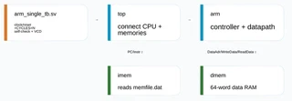
arm_single.sv
    processor + memories
    ├── top
    ├── arm
    │   ├── controller
    │   └── datapath
    ├── imem
    └── dmem

arm_single_tb.sv
    clock generation
    reset generation
    +CYCLES=N run-time control
    success self-check
    waveform dumping

memfile.dat
    ARM machine-code program
The exact supplied processor uses:
initial
    $readmemh("memfile.dat", RAM);
inside imem. The revised testbench already contains:
$dumpfile("arm_single.vcd");
$dumpvars(0, testbench);
Therefore do not manually add $dumpfile or $dumpvars to the processor source.
20. Hands-on 3C — Compile and Run the Processor
Procedure
- Confirm the folder contains:
arm_single.sv
arm_single_tb.sv
memfile.dat
- Compile both SystemVerilog files together:
iverilog -g2012 -Wall -s testbench \
  -o arm_single.out arm_single.sv arm_single_tb.sv
- Run for 25 active processor cycles:
vvp arm_single.out +CYCLES=25
Observe the terminal messages. A successful run should report that the success condition was seen and then complete at the selected cycle limit.
Confirm the waveform was generated:
ls -l arm_single.vcd
- Open it:
gtkwave arm_single.vcd
What the compile options mean
-g2012— enable SystemVerilog 2012 syntax used by the source.-Wall— enable a broad set of Icarus warnings.-s testbench— selecttestbenchas the top-level root module.-o arm_single.out— name the compiled simulation.- both
.svfiles are listed because the design and testbench are separate.
Expected result: the testbench watches for a store of decimal
7to byte address0xF8. It records success but continues until the requested number of post-reset cycles has completed.
21. Runtime Cycle Control and Recompilation Rules
The revised testbench reads a plusarg at run time:
vvp arm_single.out +CYCLES=10
vvp arm_single.out +CYCLES=25
vvp arm_single.out +CYCLES=50
vvp arm_single.out +CYCLES=100
If the argument is omitted:
vvp arm_single.out
the testbench uses:
DEFAULT_CYCLES = 25
21.1 What CYCLES counts
CYCLES counts rising-edge processor cycles after reset is released.
The supplied testbench uses:
clock period = 10 ns
reset high for first 22 ns
The first active rising edge is therefore after the reset pulse has ended.
21.2 When to recompile
Recompile with iverilog when:
arm_single.svchanges;arm_single_tb.svchanges.
Run again:
iverilog -g2012 -Wall -s testbench \
  -o arm_single.out arm_single.sv arm_single_tb.sv
Do not recompile when only +CYCLES=N changes. Simply rerun:
vvp arm_single.out +CYCLES=50
21.3 What if only memfile.dat changes?
You also do not need to recompile. $readmemh("memfile.dat", RAM) is executed when the simulation starts, so the next vvp run reads the current contents of memfile.dat.
Use:
vvp arm_single.out +CYCLES=25
again after regenerating memfile.dat.
22. GTKWave Inspection of the ARM Execution
Open:
gtkwave arm_single.vcd
22.1 Navigate the hierarchy
- In the hierarchy pane, expand
testbench. - Select
dutfor top-level processor-system signals. - Expand
dut.armanddut.arm.dpif you want deeper datapath signals. - Append the required traces to the waveform panel.
22.2 Recommended signals
Start with:
clk
reset
dut.PC
dut.Instr
dut.DataAdr
dut.WriteData
dut.MemWrite
dut.ReadData
The presentation also recommends useful internal signals where available:
dut.arm.ALUResult
dut.arm.dp.ReadData
dut.arm.dp.SrcA
dut.arm.dp.SrcB
dut.arm.dp.ALUResult
22.3 Change buses to hexadecimal
For 32-bit buses, hexadecimal is easier to compare with assembly and memfile.dat.
In GTKWave:
- select a bus trace;
- right-click;
- choose Data Format → Hex.
GTKWave documentation supports displaying multi-bit vectors in bases including hexadecimal.
22.4 Zoom and follow the instruction stream
Use Zoom Full first. Then zoom around the final MemWrite pulse.
Look for:
resetstarting high and then falling low;PCprogressing through byte addresses0x00,0x04,0x08, …;Instrmatching the successive 32-bit words inmemfile.dat;- store pulses on
MemWrite; ReadDatashowing3and4during the twoLDRinstructions;- the ALU result becoming
7afterADD R3, R1, R2; - the final successful store.
23. Expected Processor Behaviour and Verification Checklist
The demonstration program is successful when this transaction appears:
MemWrite   = 1
DataAdr    = 0x000000F8
WriteData  = 0x00000007
Why 0xF8?
word index = 62
byte address = 62 × 4 bytes
             = 248 decimal
             = 0xF8
The data memory uses:
RAM[a[31:2]]
so the external byte address 0xF8 selects internal word 62.
Verification checklist
-
resetbegins high and then goes low. -
PCstarts at0after reset and normally advances by four bytes per instruction. -
Instrfollows the words inmemfile.dat. -
MemWritepulses forSTR R1,[R0,#0]. -
MemWritepulses forSTR R2,[R0,#4]. -
ReadDatashows0x00000003during the first load. -
ReadDatashows0x00000004during the second load. - the ADD result reaches
0x00000007. - the final store has
DataAdr = 0x000000F8. - the final store has
WriteData = 0x00000007. - the testbench prints that the success condition was observed.
- the
B haltinstruction causes repeated execution of the halt loop until the cycle limit ends the simulation.
Minimum useful GTKWave trace:
clk,reset,PC,Instr,DataAdr/ALUResult,WriteData,MemWrite, andReadData, with 32-bit buses displayed in hexadecimal.
24. Troubleshooting
arm-none-eabi-gcc: command not found
Check that you opened MSYS2 UCRT64, then install the Arm GCC package:
pacman -S mingw-w64-ucrt-x86_64-arm-none-eabi-gcc
Close and reopen UCRT64 if the path still has not refreshed.
iverilog: command not found or vvp: command not found
Install the Icarus UCRT64 package:
pacman -S mingw-w64-ucrt-x86_64-iverilog
The package includes both executables.
Unable to open memfile.dat / $readmemh error
The instruction memory opens memfile.dat using a relative path. Run vvp from the folder containing the file:
pwd
ls -l arm_single.sv arm_single_tb.sv memfile.dat
Then run:
vvp arm_single.out +CYCLES=25
File appears missing even though you saved it in Notepad
Windows may have saved a hidden .txt extension. Check:
ls -l
Look for names such as add.c.txt or simple_alu.v.txt.
Verilog syntax error in the ALU exercise
Check:
- semicolons;
- matching
begin/end; case/endcase;module/endmodule;- straight ASCII quotation marks;
- exact literal syntax such as
2'b00.
arm_single.vcd is not created
The revised testbench already contains the VCD dump statements. Check that:
arm_single_tb.svwas included in the compile command;-s testbenchselected the correct top module;- compilation succeeded;
- you actually ran
vvp arm_single.out ....
Do not add another $dumpfile or $dumpvars to arm_single.sv.
GTKWave opens but no traces are visible
Opening a VCD does not automatically append every signal to the wave panel. Select the appropriate hierarchy, select the signals, and use Append or Insert.
Bus values are hard to read
Change 32-bit buses to hexadecimal:
Right-click → Data Format → Hex
Unknown x values appear
Uninitialized registers or memory words can legitimately appear as x until they are written. In this processor, the data RAM is not pre-initialized. The demo program explicitly writes 3 and 4 before loading those locations.
If x values remain on values that should already have been initialized, verify the instruction sequence and the earlier write pulses.
The final value is wrong
Check in this order:
cat memfile.datand compare it with the expected ten words;- verify
simple_sum.sexactly matches the workshop program; - confirm the simulation ran long enough;
- inspect
PCandInstrto ensure the program is being fetched correctly; - inspect the two initialization stores;
- inspect the two loads (
ReadData = 3, then4); - inspect the ADD result;
- inspect the final
MemWrite,DataAdr, andWriteDatatogether.
The C-generated assembly differs from the handout
That is expected. Compiler version and optimization choices affect prologues, temporary registers, and exact instruction sequences. Identify the function label, addition, result placement, and return semantics rather than comparing every line.
Fast recovery sequence
pwd
ls -l
arm-none-eabi-gcc --version
arm-none-eabi-objdump --version
iverilog -V
vvp -V
25. Suggested Exercises and Extensions
These are deliberately small extensions. Keep the same workflow: predict → edit → compile → simulate → inspect → explain.
Exercise A — change the ALU inputs
Change:
a = 4'd9;
b = 4'd2;
Predict before simulating.
Expected values:
ADD = 11
SUB = 7
AND = 0
OR  = 11
Explain 9 AND 2 bit by bit using:
1001
0010
----
0000
Exercise B — demonstrate XOR
A 2-bit selector already has only four encodings. For a minimal demonstration, temporarily replace AND:
2'b10: y = a ^ b;
A more complete extension would widen op and update the testbench.
Exercise C — add a zero flag
Add an output and drive it high whenever y is zero:
output zero;
assign zero = (y == 4'b0000);
Then update the testbench and inspect zero in GTKWave.
Exercise D — change only the processor run length
Without changing source files, compare:
vvp arm_single.out +CYCLES=10
vvp arm_single.out +CYCLES=25
vvp arm_single.out +CYCLES=50
Which run first contains the successful store? Why is recompilation unnecessary?
Exercise E — relate machine code to waveform
Pick one instruction from memfile.dat, find the same value on dut.Instr, and explain what changes in the datapath during that cycle.
Beyond this workshop
A natural curriculum path is:
ALU
  ↓
register file
  ↓
control decoder
  ↓
memory interface
  ↓
single-cycle processor
  ↓
instruction extension / FPGA project
The supplied educational processor is intentionally a stepping stone rather than an endpoint.
26. Summary and References
Three takeaways
- Code becomes instructions. A compiler translates C into instructions encoded for a target architecture.
- Datapaths execute instructions. Registers, ALU, memory interfaces, multiplexers, and control logic cooperate to change architectural state.
- Verilog/SystemVerilog makes hardware observable. A design plus a testbench can be compiled, simulated, and inspected before hardware implementation.
Workshop and textbook reference
- Sarah L. Harris and David Money Harris, Digital Design and Computer Architecture: ARM Edition, 1st ed., Morgan Kaufmann/Elsevier, 2015. The presentation uses Chapters 6–7 as its conceptual foundation.
Official technical references
- Arm, ARM Architecture Reference Manual, ARMv7-A and ARMv7-R edition, DDI 0406: Arm Developer documentation
- GCC, ARM target options: GCC ARM Options
- GCC, overall compilation options including
-S: GCC Overall Options - Icarus Verilog: Getting Started
- Icarus Verilog: Command-Line Flags
- GTKWave: Official project page and documentation
- MSYS2: Installer
- MSYS2: Environments
- MSYS2: Package Management
- MSYS2 UCRT64 packages: GCC, Arm GCC, Icarus Verilog, GTKWave